Meshes VS Nurbs
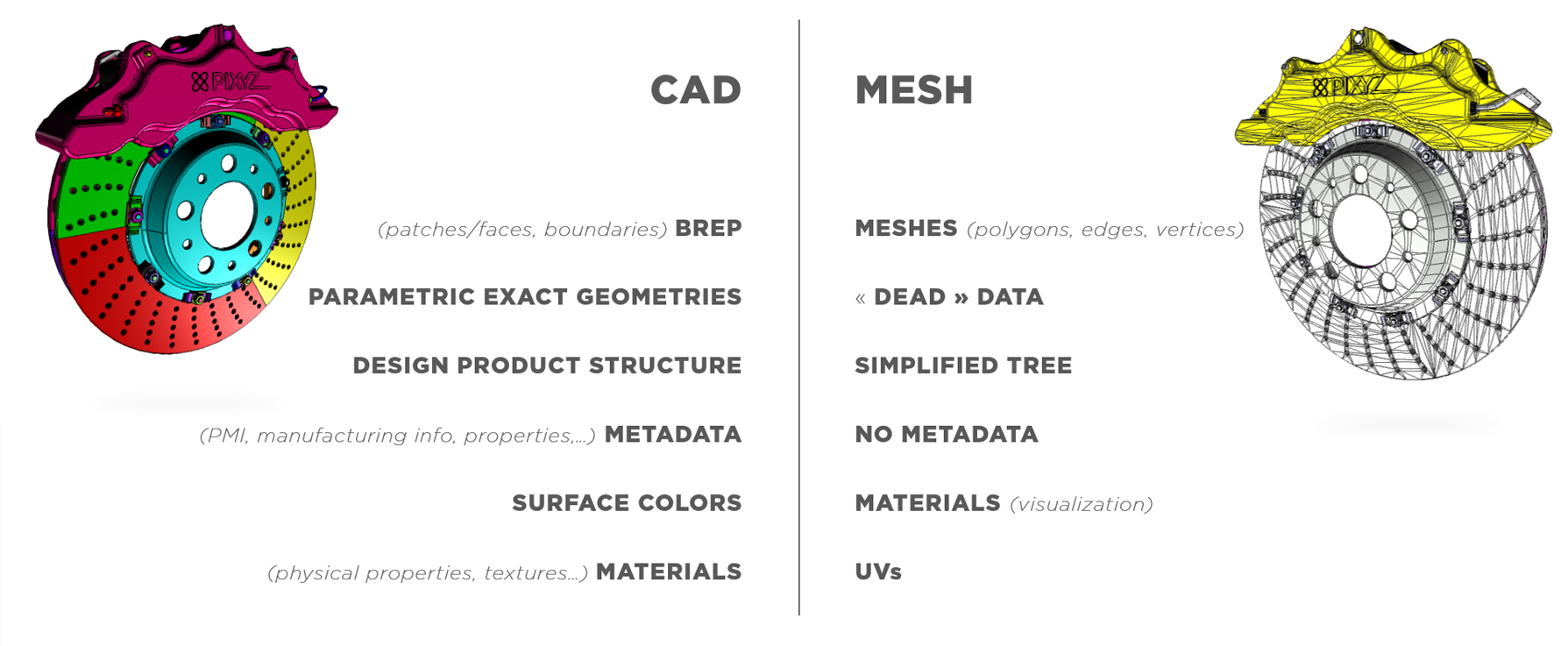
CAD models inherited from CAD software (CATIA, NX, SolidWorks, Alias, STEP…) are not tessellated. They contain exact parametric/mathematical surfaces (BREP, Nurbs,...).
A CAD body (closed volume) or CAD surface (open shell surface) is composed of CAD faces (or patches), delimited by boundaries (see Glossary).
To be displayed in a 3D application, these CAD faces need to be translated into meshes. A mesh is composed of multiple connected polygons, or triangles (1 polygon = 2 coplanar triangles), forming a mesh surface that is understandable by a GPU, to be rendered in a 3D application.
Moreover, CAD models can contain additional engineering and design data (metadata, PMI,…), that can be very useful to perform a targeted Data Preparation process based on targeted properties.
DCC software (Maya, 3DS Max, Blender,…) natively create tessellated geometries, or meshes/polygonal surfaces, that can be exported as FBX files (for example) to be re-imported in Unity3D using Pixyz Plugin for Unity. Note that these meshes often come with UVs (1st channel and/or 2nd channel), that can either be kept at import, or overridden using the “Generate UVs” setting (1st channel only).
Existing tessellated meshes can be optimized to create LODs by performing efficient and conservative decimation on them.
NOTE Useful links about CAD vocabulary: CAD, BREP, Nurbs, PMI.