About 3D Models Types
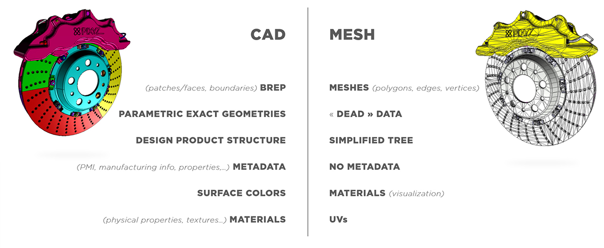
CAD models inherited from CAD software (CATIA, NX, SolidWorks, Alias, STEP…) are not tessellated. They contain exact parametric geometries, also called BRep, Nurbs, CSG...
A CAD body (closed volume) or CAD surface (open shell surface) is composed of CAD faces (also called patches), delimited by boundaries (see Glossary).
NOTE Useful links about CAD vocabulary: CAD, BRep, Nurbs, PMI, CAD Data Exchange.
To be displayed in a 3D application, CAD faces need to be translated into tessellated surfaces, also called meshes.
A mesh is composed of multiple connected polygons, or triangles (1 polygon generally equals 2 coplanar triangles), forming a discretized geometry that is understandable by a GPU, to be rendered in a 3D application.
Moreover, CAD models can contain additional engineering and design data (Metadata, PMI,…), that can be very useful to perform a targeted Data Preparation process based on targeted properties.
DCC software (Maya, 3DS Max, Blender, Modo…) natively create tessellated geometries (often referred as polygonal models), that can be exported as FBX files for example, to be re-imported in Pixyz Studio for further optimization.
Note that these meshes often come with attributes like normals and UVs (textures coordinates used to display textures on meshes), that can either be kept or recreated in Pixyz Studio.
NOTE To learn about a mesh and its attributes, have a look at the page Anatomy of a Mesh in Unity documentation! See also Polygon Mesh and About Face and Vertex Normals